Spend an hour crimping cable ends, plug everything in, and... nothing works. You check the connectors—they look fine. Then you compare both ends and realize you mixed up the color order. Now you're pulling the cable out and starting over.
Inside every Cat 5 cable, eight copper wires follow a color system that's been around since the 1990s. Match these colors correctly, and your network transmits data flawlessly. Mix them up, and you'll chase phantom connection issues for hours.
Understanding Cat 5 Cable Color Standards
Back in 1991, the Telecommunications Industry Association introduced two wiring schemes: T568A and T568B. Both work perfectly fine—you just need to pick one and stick with it across your entire network.
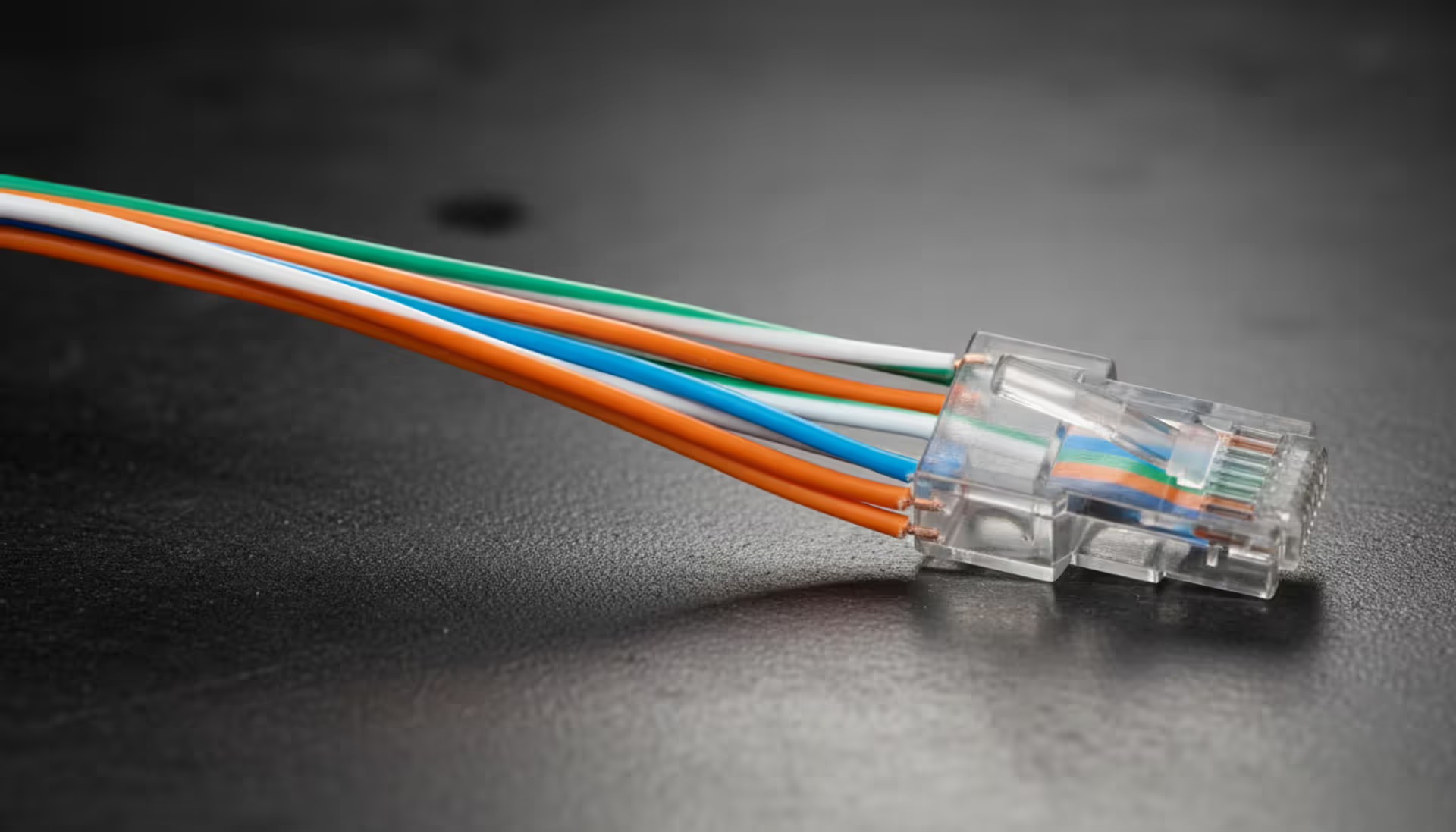
Here's what matters: each cable contains four pairs of twisted wires. One wire in each pair has solid color insulation (orange, green, blue, brown). Its partner wire is mostly white with a stripe matching that solid color. So you get white-with-orange-stripe paired with solid orange, white-with-green-stripe paired with solid green, and so on.
T568A puts the green pair on positions 1 and 2 at the connector. T568B flips things around—orange takes those first two spots instead. Everything else? Pretty much the same between both standards.
Walk into most office buildings in the US, and you'll find T568B everywhere. Government facilities often use T568A (some federal specs actually require it). Homes? Complete mix. I've seen houses wired with T568A, houses with T568B, and houses where someone used both because they didn't know any better.
Why does the color order matter so much? Your network switch sends data out on specific pins and listens for incoming data on other pins. Pin 1 and 2 form your transmit pair. Pins 3 and 6 handle receiving. If you wire those positions with split pairs—like putting white-orange on pin 1 but pairing it with green on pin 2—the twisted pair geometry falls apart. Those two wires no longer cancel out electrical interference the way they should.
The color stripes give you a visual sanity check before crimping. Lay those eight wires flat in proper sequence, and you can spot problems immediately. See blue where orange should be? Fix it now, not after you've sealed the connector.
Author: Logan Kessler;
Source: baltazor.com
Cat 5 vs Cat 6 Cable Colors
You can't tell Cat 5 from Cat 6 by looking at wire colors. Both use identical color coding—same whites with colored stripes, same solid colors, same sequence for T568A or T568B.
Strip the jacket off both cables side-by-side, though? You'll notice Cat 6 feels thicker and stiffer. Most Cat 6 cable measures about a quarter-inch across compared to Cat 5's roughly 0.2 inches. That extra thickness comes from a plastic crossweb running down the cable's center, keeping the four pairs physically separated from each other.
Some Cat 6 manufacturers skip the crossweb and just add thicker insulation around each wire instead. Either way, you're getting a beefier cable that doesn't bend as easily through tight spaces. Try routing Cat 6 through narrow wall cavities or behind shallow patch panels, and you'll understand why installers sometimes miss Cat 5's flexibility.
Shielded Cat 6 adds foil wrapping around the pairs but keeps the same color arrangement underneath. Peel back that foil, and you're looking at the same white-orange, orange, white-green, green, white-blue, blue, white-brown, brown combination.
Feature
Cat 5
Cat 6
Jacket Width
~0.204 inches
~0.250 inches
Maximum Distance
328 feet (100 meters)
328 feet (100 meters)
Bandwidth
100 MHz
250 MHz
Top Speed
1 Gbps
10 Gbps
Internal Separator
Not included
Usually present
Color Standards
T568A or T568B
T568A or T568B
How to Wire Cat Cable Using Color Codes
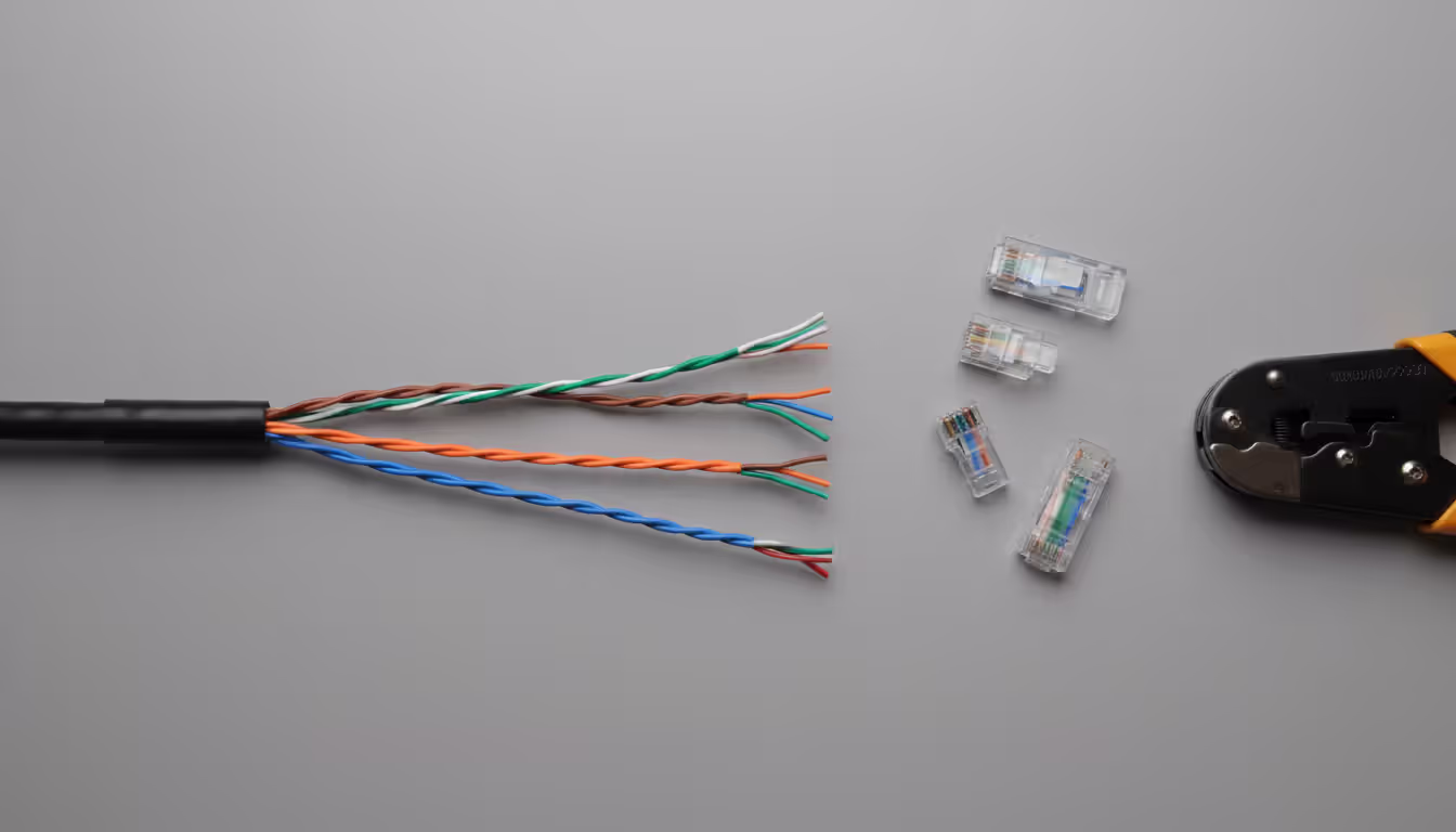
You need four things for this: cable stripper, RJ45 connectors, crimping tool, and patience. Your first few attempts will probably fail—that's normal. Buy extra connectors.
First, figure out which standard your building already uses. Grab an existing cable, hold the connector with the plastic tab pointing down and the gold contacts facing you. Left-most wire is white-green? That's T568A. White-orange? You're looking at T568B.
Strip about an inch and a half of outer jacket. Don't use a knife unless you've done this a thousand times—you'll nick the wire insulation underneath. Cable strippers have a circular blade that cuts just deep enough to score the jacket without touching the wires inside.
You'll see the four pairs twisted together. Untwist them only as much as you absolutely need to arrange them in order. Every inch you untwist degrades signal quality, especially past 100 Mbps speeds. Keep untwisted sections under half an inch.
T568A Wiring Pattern
Hold your connector with the tab down and contacts toward you. Wires go in this sequence from left to right:
Position 1: White wire with green stripe Position 2: Solid green Position 3: White wire with orange stripe Position 4: Solid blue Position 5: White wire with blue stripe Position 6: Solid orange Position 7: White wire with brown stripe Position 8: Solid brown
Positions 1, 2, 3, and 6 carry data in standard 10/100 networks. Gigabit networks use all eight wires, so even though positions 4, 5, 7, and 8 sit idle on slower networks, you still need them wired correctly for future upgrades.
T568B Wiring Pattern
Same connector orientation. Different color sequence:
Position 1: White wire with orange stripe Position 2: Solid orange Position 3: White wire with green stripe Position 4: Solid blue Position 5: White wire with blue stripe Position 6: Solid green Position 7: White wire with brown stripe Position 8: Solid brown
Notice positions 4, 5, 7, and 8 never change between standards. Only the first three positions and position 6 swap around. Blue pair and brown pair always land in the same spots regardless.
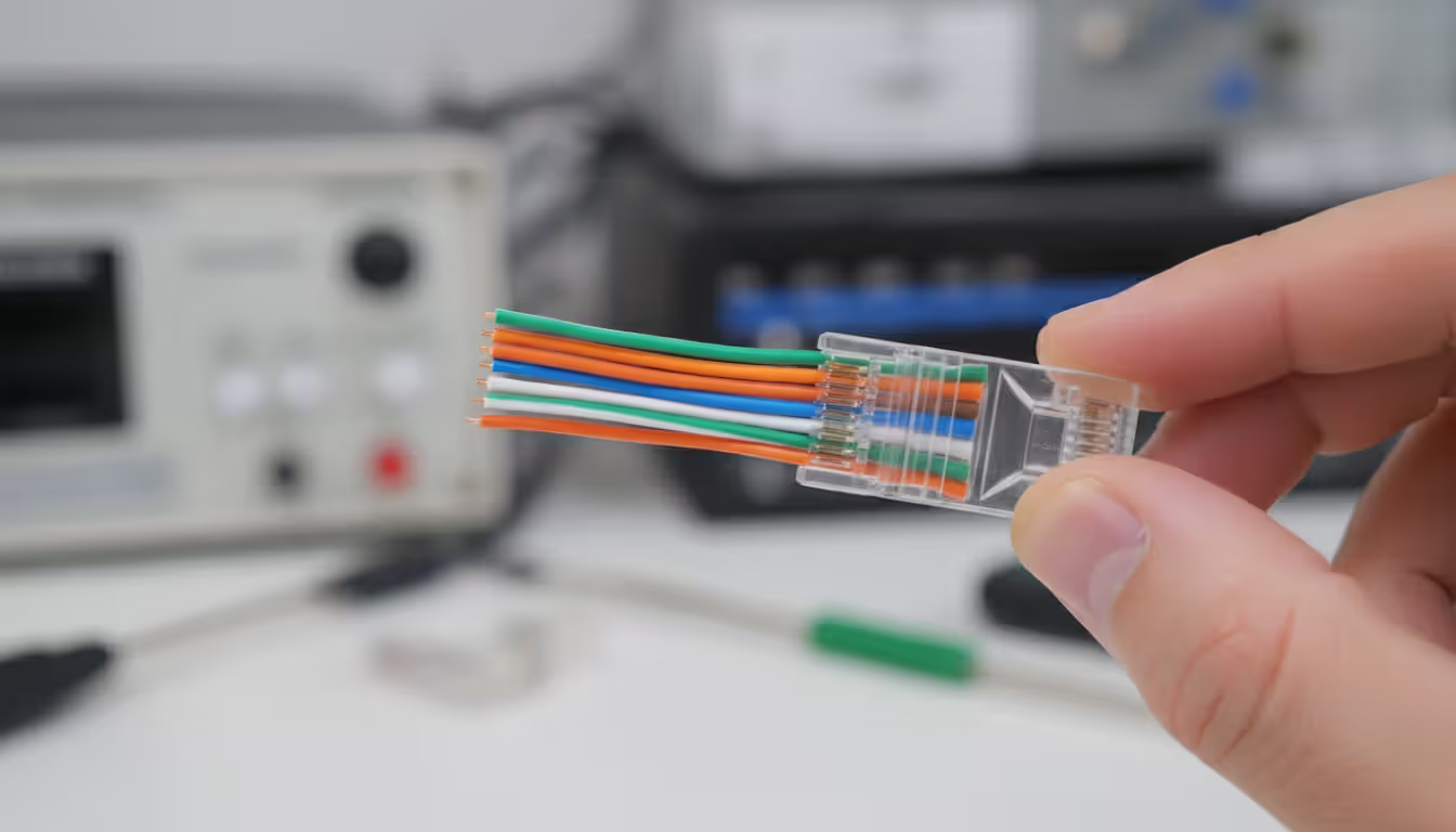
After arranging wires correctly, flatten them together and cut straight across about half an inch from the jacket edge. All eight wire tips must be exactly even—if one wire is shorter, it won't reach its pin inside the connector.
Push the wires into the connector while keeping them flat and in sequence. The outer jacket should slide at least a quarter-inch into the connector body. That jacket-inside-connector situation is your strain relief. Without it, the first time someone tugs the cable, individual wires pull loose from their pins.
Author: Logan Kessler;
Source: baltazor.com
Cat 6 Cable Installation Best Practices
Thick cable needs gentle curves. Calculate minimum bend radius by multiplying cable diameter by four. Cat 6 at 0.25 inches diameter needs at least a one-inch radius on any bend. Tighter corners crush the internal crossweb or distort wire pair geometry enough to fail certification testing.
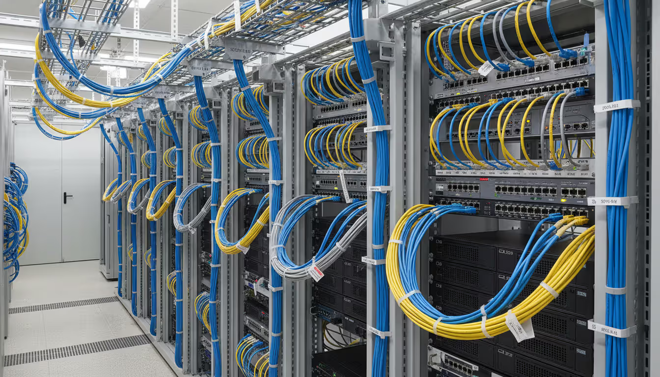
Support horizontal runs every four to five feet using J-hooks or cable trays. Support vertical runs every three to four feet. Unsupported cable eventually sags under its own weight, pulling on connection points until something comes loose. Avoid zip ties—they create pressure points that deform the cable. J-hooks let cable rest naturally without pinching.
Here's something installers frequently mess up: they untwist several inches of pairs to make arranging colors easier, then cut away the excess before crimping. Those extra untwisted inches still existed briefly in your cable run, and now you've got a section with degraded electromagnetic characteristics. Each pair twists at a different rate inside the cable—typically three to four twists per inch, varying by pair. These different twist rates prevent pairs from interfering with each other. Preserve those twists up to within half an inch of termination points.
Keep Cat 6 at least twelve inches away from AC power lines and six inches from fluorescent light fixtures. Electrical fields from power sources inject noise into data cables, particularly during long parallel runs. When cables must cross power lines, cross at ninety-degree angles to minimize exposure length.
Label everything before closing up walls. Seriously. I've watched network techs spend entire afternoons tracing mystery cables through ceiling spaces. Write labels identifying source and destination on both cable ends. Something like "3FL-OFFICE-12B-TO-MDF-SW2-P08" tells you immediately this cable runs from third floor office 12B to the main distribution frame, switch 2, port 8.
Author: Logan Kessler;
Source: baltazor.com
Cat 6 Cable Length Limit and Performance
Don't run Cat 6 cable more than 328 feet (100 meters) for Ethernet connections. That measurement includes your main cable plus patch cords at both ends—standard practice allocates 295 feet of permanent cable with 16-foot patch cables connecting equipment on each end.
Electrical signals weaken as they travel through copper. Digital pulses need enough voltage at the receiving end for equipment to correctly identify ones and zeros. Beyond 100 meters, weakened signals drop below reliable detection thresholds. You get packet losses and retransmissions that slow everything down.
This 328-foot limit applies whether you're running 100 Mbps or 10 Gbps. Higher frequencies weaken faster than lower frequencies, which is why Cat 6 manufacturing tolerances are so much tighter than Cat 5—better construction compensates for increased signal loss at higher speeds.
Pushing past the length limit doesn't cause instant failure. You might connect successfully at 350 feet. You might even transfer files without obvious problems. But network monitoring tools will show CRC errors and retransmissions eating into your actual throughput. Under heavy traffic, you'll see sporadic disconnections that reconnect seconds later.
Need to go farther than 100 meters? Insert a network switch or repeater at the midpoint. These devices receive your weakened signal, decode the data, and retransmit fresh signals good for another 100 meters. One switch doubles your reach to 200 meters with 100-meter segments on either side.
Temperature affects cable distance. Hot environments increase copper resistance, accelerating signal degradation. Cables running through uncooled attic spaces or near heat sources might fail testing at distances that would work fine in air-conditioned spaces. Build in a 10-15% distance margin for cables in challenging thermal environments.
Common Cat Cable Wiring Mistakes
Author: Logan Kessler;
Source: baltazor.com
Split pairs cause more troubleshooting nightmares than any other wiring error. This happens when you break up matched pairs—like connecting white-orange to green instead of orange. Basic continuity testers show all eight wires reaching their assigned pins, so the cable looks good. But under actual network traffic, it performs terribly or doesn't work at all.
Why? Twisted pair technology depends on electromagnetic field cancellation. Current flowing through a wire creates a magnetic field. When that wire's partner carries current in the opposite direction, their magnetic fields cancel out. Split a pair, and you've destroyed this cancellation effect. Now each wire acts as an antenna picking up interference from nearby electrical sources.
Split pairs typically occur when someone arranges wires by individual color rather than maintaining pair relationships. They'll group all the striped wires together (white-orange, white-green, white-blue, white-brown), followed by all solid colors (orange, green, blue, brown). Looks organized. Doesn't work.
Excessive untwisting ranks second on the mistake list. Some installers untwist three or four inches to simplify color arrangement, figuring they'll cut away most of it before crimping anyway. Those extra inches of exposed, separated wire pick up interference that properly twisted pairs would reject. Half an inch untwisted is already pushing it. More than that? You're asking for problems.
Using different standards on opposite cable ends creates an accidental crossover cable. Terminate one end T568A and the other T568B, and you've swapped transmit and receive pairs. Modern equipment with auto-MDIX (automatic medium-dependent interface crossover) can adapt to this situation, but older devices simply won't establish a link. Worse, your cable works with some equipment while failing with others, creating intermittent problems that drive troubleshooting in circles.
Nicking wire insulation while stripping the outer jacket produces delayed failures that appear weeks or months later. Minor cuts through insulation might not prevent initial operation, but exposed copper oxidizes over time. The cable works fine for a while, then develops random errors without apparent cause. Locating these failures without time-domain reflectometry equipment becomes nearly impossible.
Crimping pressure matters. Excessive force crushes wires flat, changing their impedance characteristics and potentially breaking strands inside the insulation. Insufficient pressure leaves wires floating in their channels, creating intermittent contacts whenever cable flexes. Quality crimping tools click or stop automatically at correct pressure. Cheap tools without this feedback require practice on scrap cable to develop feel for proper technique.
Color codes aren't cosmetic—they're physics. Twisted pairs eliminate interference through precise electromagnetic interaction. Wrong colors turn your cable into an interference antenna instead of a data conduit
— Marcus Chen
Frequently Asked Questions
Does it matter which color standard I use for Cat 5 cables?
Pick T568A or T568B—either works equally well. What matters is consistency. Wire every cable in your installation using the same standard. Most commercial buildings use T568B, while some government facilities specify T568A in their contract requirements. Choose based on what's already installed around you, or flip a coin if you're starting fresh. Just don't mix standards.
Can I mix T568A and T568B on the same cable?
Terminating opposite ends with different standards produces a crossover cable that reverses transmit and receive pairs. This configuration was useful back when connecting two computers directly together, before switches handled it automatically. Modern network adapters include auto-MDIX to correct crossed cables, so you'll probably get away with it. But why introduce potential compatibility problems? Use matching standards on both ends.
Are Cat 5 and Cat 6 cable colors the same?
Absolutely identical. Both categories follow the same T568A or T568B color patterns. You cannot identify cable category by examining wire colors. Look for physical differences instead—Cat 6 is thicker overall and usually contains an internal separator spine. The eight-wire color arrangement stays constant across all twisted-pair Ethernet categories from Cat 5 through Cat 8.
What happens if I wire the colors in the wrong order?
Random color ordering typically prevents connections from working at all. Network devices expect specific pairs on particular pins for transmit and receive functions. Scramble the wire order, and even though you might pass a basic continuity test, you won't create functional data links. Split pairs—where you separate matched wires—are worse. The cable appears to work but experiences massive crosstalk and packet losses under load.
How far can I run Cat 6 cable before signal loss?
Maximum distance is 328 feet (100 meters) including patch cables at both ends. This applies to all speeds from 100 Mbps through 10 Gbps. Go beyond 100 meters and signal degradation causes packet losses plus unstable connections. Install a network switch or repeater to regenerate signals when covering greater distances. Each active device resets your 100-meter budget.
What is the diameter difference between Cat 5 and Cat 6 cables?
Cat 5 runs roughly 0.204 inches across. Cat 6 measures around 0.250 inches—about 20% thicker. This size increase accommodates an internal divider spine or enhanced insulation that reduces interference between wire pairs. The thickness difference impacts minimum bend radius requirements and determines how many cables fit through conduit or cable management channels.
Getting wire colors right prevents the electromagnetic interference and signal degradation that cripple network performance. T568A and T568B sequences guarantee twisted pairs stay properly matched from one connector to the other, preserving the electromagnetic field cancellation that enables high-speed data transmission.
Cat 5 and Cat 6 share identical color specifications despite their physical construction differences. Cat 6's increased thickness and internal separator require more careful bending and handling, but both categories observe the same 100-meter distance limitations and color standards.
Success comes from consistency. Choose T568A or T568B based on your existing infrastructure, then apply that configuration to every termination in your network. Minimize wire untwisting, support cables properly, and verify your work before concealing installations behind walls. Follow these practices, and your color-coded copper will deliver rated performance reliably for decades.
Virtual desktop infrastructure represents a fundamental shift in how organizations deliver computing resources. Learn about VDI architecture, deployment models (on-premises, cloud, hybrid), implementation costs, use cases, and how to select the right solution for remote work and centralized management needs
Network administrators who rely on hourly snapshots discover problems only after users complain. A real time network traffic monitor shows what's happening at this exact moment—every packet, every connection, every anomaly as it occurs. Learn how these systems work and how to implement them effectively
Public cloud storage has become the backbone of modern data infrastructure, powering everything from smartphone photo backups to enterprise disaster recovery systems. Learn how it works, key benefits and limitations, security considerations, and how to choose the right provider for your needs
Choosing between on-premise and cloud infrastructure affects budget, security, compliance, and agility. Understand cost structures, security trade-offs, and migration planning to make informed decisions aligned with your business requirements and strategic goals
The content on this website is provided for general informational and educational purposes only. It is intended to explain concepts related to cloud computing, computer networking, infrastructure, and modern IT systems.
All information on this website, including articles, guides, and examples, is presented for general educational purposes. Technology implementations may vary depending on specific environments, business needs, infrastructure design, and technical requirements.
This website does not provide professional IT, engineering, or technical advice, and the information presented should not be used as a substitute for consultation with qualified IT professionals.
The website and its authors are not responsible for any errors or omissions, or for any outcomes resulting from decisions made based on the information provided on this website.