The shift from copper to fiber optic infrastructure has reshaped American telecommunications in ways few predicted twenty years ago. Today's suburban home might receive faster internet than a Fortune 500 company headquarters had in 2005. If you're evaluating fiber optic systems—whether for a small office upgrade or a municipal network expansion—understanding the practical realities beyond the marketing hype makes the difference between a solid investment and an expensive learning experience.
What Is Fiber Optic Technology and How Does It Work
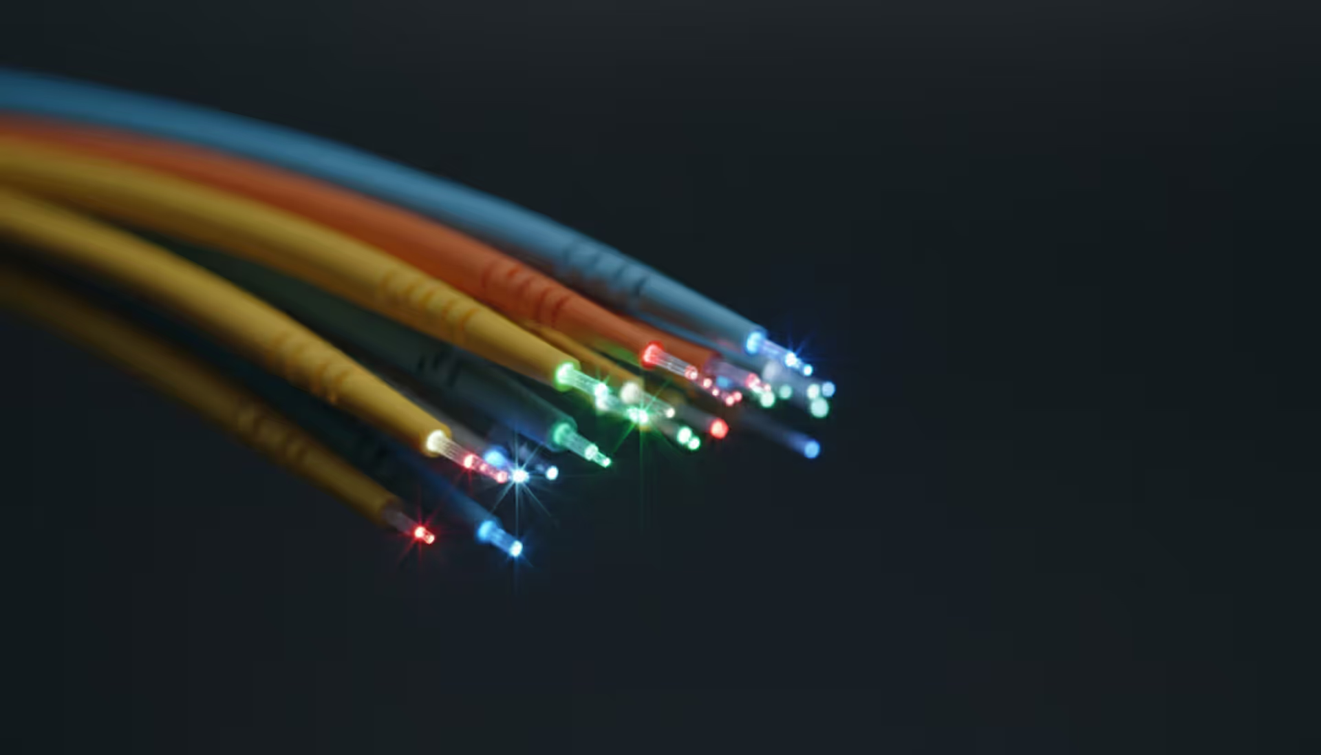
Think of fiber optic cables as incredibly sophisticated flashlights. Data moves through these systems as rapid light pulses traveling inside glass threads—each strand measuring roughly 125 microns across (about the width of a thick human hair, though the functional core runs even narrower).
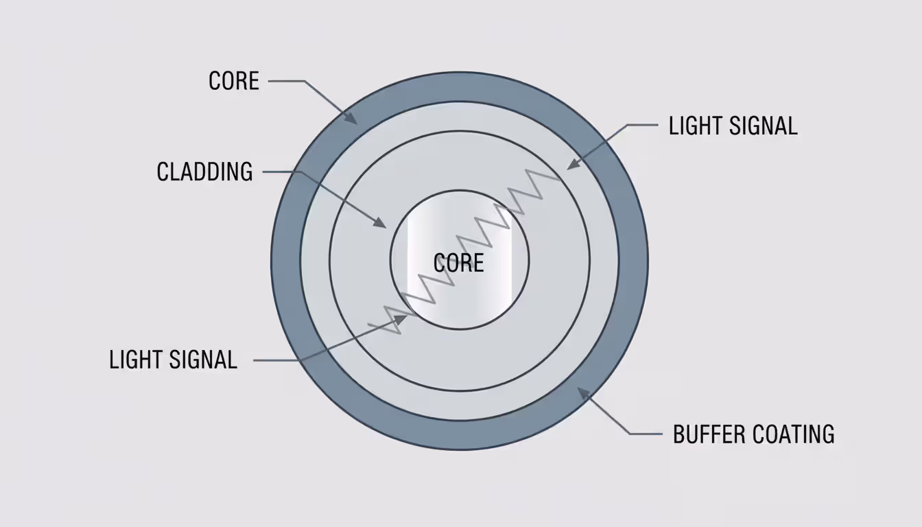
The engineering relies on three layers working together. At the center, the core provides the pathway for light signals. Surrounding this core, the cladding layer has a different optical density that acts like a mirror, keeping light from escaping. Finally, a protective buffer coating shields everything from moisture, impacts, and handling damage during installation.
Here's where physics gets practical: light bounces along the core through a principle called total internal reflection. Picture a flashlight beam hitting a mirror at a shallow angle—it reflects rather than passing through. Inside fiber cables, light rays strike the boundary between core and cladding at precise angles that force them to bounce back inward rather than escape outward. This controlled reflection lets signals travel extraordinary distances—we're talking dozens of miles—before they need amplification. Copper cables? They start losing signal strength after a few hundred feet.
Single-mode fiber narrows the core to just 8-10 microns (about one-tenth the width of a typical human hair). This microscopic pathway forces light to travel in essentially one straight line, eliminating the signal distortion you'd get from multiple overlapping light paths. Telecom companies building networks between cities almost always choose single-mode because it handles distances exceeding 40 kilometers between amplifiers. The catch? You need expensive laser light sources. The payoff? Crystal-clear signals across continents.
Author: Logan Kessler;
Source: baltazor.com
Multi-mode fiber opens up the core to 50 or 62.5 microns. That wider pathway accepts multiple light rays bouncing at different angles simultaneously—hence "multi-mode." This design works beautifully with cheaper LED light sources, making it the go-to choice for shorter campus networks and data centers. You'll typically see multi-mode deployments for distances under 550 meters. Push it further and the multiple light paths start interfering with each other (engineers call this "modal dispersion"), which limits your bandwidth.
Modern systems squeeze absurd amounts of data through a single fiber strand. Lab environments have demonstrated throughput exceeding 1 petabit per second—that's 1,000 terabits—though commercial deployments in 2026 more commonly deliver 400 to 800 gigabits per wavelength channel when using advanced multiplexing. Still impressive when you consider the entire Netflix catalog could theoretically transfer in seconds.
Types of Fiber Optic Network Systems
Fiber to the Home (FTTH) delivers what the name promises—optical cable running directly to individual houses. An optical network terminal (ONT), typically mounted on an exterior wall or tucked in a garage, handles the conversion from light pulses to standard electrical Ethernet signals. Some US markets now offer symmetrical 10 Gbps residential plans, though most homeowners stick with 1-2 Gbps packages that already exceed what most devices can fully utilize.
Fiber to the Premises (FTTP) works as the umbrella term covering both homes and businesses. A company campus might receive FTTP service feeding into a private fiber optic network that interconnects multiple buildings from one central entry point. Unlike residential broadband where you're sharing bandwidth with neighbors, business FTTP typically provides dedicated capacity—you get what you pay for without contention ratios reducing performance during peak hours.
Author: Logan Kessler;
Source: baltazor.com
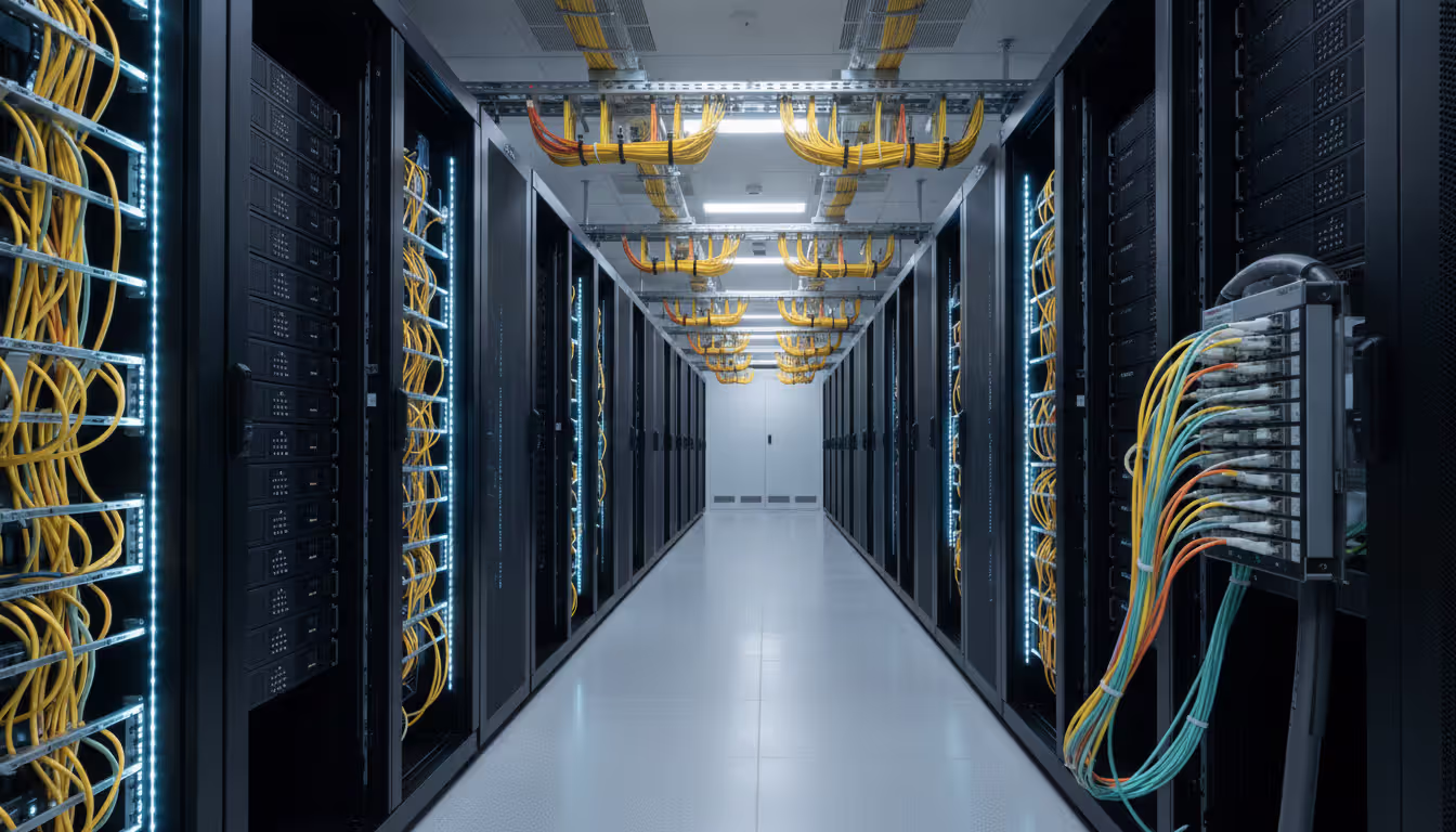
Enterprise networks within corporate environments use fiber optic networking to link switches, routers, servers, and storage systems. Walk through a modern data center and you'll see fiber everywhere. A typical setup might deploy single-mode fiber for connections between buildings separated by half a kilometer to several miles, while multi-mode fiber handles the shorter hops within individual telecommunications closets and equipment rows.
Backbone infrastructure forms the skeleton of internet connectivity that most people never see. Long-haul fiber optic networks cross state lines and follow railroad tracks or interstate highway rights-of-way. Metropolitan area networks (MANs) create fiber rings around business districts and residential zones, building in redundancy so service continues even if construction crews accidentally cut through a cable—and they will, eventually.
Under the oceans, submarine fiber optic cables carry over 95% of the data moving between continents. These specialized cables bundle multiple fiber pairs with power conductors feeding undersea repeaters, all wrapped in heavy armor protecting against ship anchors and curious sharks. The latest transatlantic systems landing at Virginia Beach and near New York handle combined capacity exceeding 300 terabits per second—basically the entire internet traffic of a major city flowing through cables lying on the seafloor.
Passive optical networks (PON) cut costs by using unpowered optical splitters that divide one fiber strand to serve multiple destinations. Picture a 1:32 splitter—one fiber from the central office feeds a splitter that serves 32 different homes. Each home shares the total bandwidth, though newer standards like XGS-PON and 50G-PON are pushing capacity high enough that sharing becomes less of a practical limitation. No electronics needed at the split point means fewer things to maintain or break.
Fiber Optic Cable Installation Process
Pre-Installation Planning and Site Assessment
Most fiber optic installation disasters happen before anyone touches a cable. Start with accurate site surveys documenting existing underground utilities, realistic building entry options, and potential obstacles you'll encounter. Every state requires calling 811 before digging—utility companies will mark underground lines, usually within 48-72 hours of your request. Skip this step and you might hit a gas line. Don't skip this step.
Choosing between aerial, underground, or indoor installation methods shapes your entire project budget and timeline. Running cables on existing utility poles (aerial installation) costs substantially less upfront but leaves your infrastructure exposed to ice storms, vehicle accidents, and that one guy who manages to back his moving truck into low-hanging lines. Underground burial via trenching or directional boring protects cables from weather and accidents but multiplies your material and labor expenses—sometimes by 3-4x compared to aerial routes.
Calculate cable lengths with generous padding—figure on 10-15% extra beyond the straight-line distance. That 500-meter span between two buildings actually needs roughly 575 meters of cable once you account for slack loops at splice points, vertical rises up building walls, and a service loop for future repairs. Order too little and you're forced to splice in additional segments, creating extra failure points and looking foolish in front of your project stakeholders.
Building codes aren't suggestions, and fire ratings matter more than you'd think. Plenum-rated cable costs 20-40% more than riser-rated alternatives, but it's required for spaces above drop ceilings where HVAC systems push air. Use the wrong cable type and you'll fail inspection, forcing a complete reinstallation on your dime. Riser-rated cable handles vertical shafts connecting floors but shouldn't go in plenum spaces. Get this wrong and you're explaining to your boss why the project budget just doubled.
Identify your splice locations and equipment mounting spots before materials arrive onsite. Fiber optic cable installation demands secure, climate-controlled spaces for splice enclosures and patch panels. That damp basement or sweltering attic will shorten equipment life expectancy and create service calls you'd rather avoid. Find proper spaces now or build them before cable day.
Installation Methods and Best Practices
Fiber cables have minimum bend radius specifications that you'll ignore at your peril. Most manufacturers specify 10-20 times the cable's outer diameter during pulls and installations, relaxing to 15 times diameter for permanent bends. Go tighter and you'll crack the glass fibers inside—not immediately visible, but signal loss appears and worsens over the following months. Nobody wants to explain why a brand-new installation is already failing.
Pulling tension matters more than most installers realize. Use proper cable grips that distribute stress across the cable's aramid strength members rather than letting tension concentrate on the delicate glass fibers. Maximum pulling force typically ranges from 200-600 pounds depending on cable construction—exceed these limits and you'll snap fibers inside an intact-looking jacket. Invest $300-800 in renting a tension monitor for difficult pulls rather than destroying $10,000 worth of cable because you were guessing.
Keep everything clean. Seriously—cleanliness ranks as the single biggest factor separating reliable installations from problem-plagued disasters. A dust particle you can barely see becomes a mountain when light tries to pass through a connection point. Run cables through conduit wherever practical. Cap every exposed fiber end immediately. Many experienced installers wear lint-free gloves when handling connectors and keep inspection scopes, alcohol wipes, and filtered compressed air within arm's reach at all times.
Author: Logan Kessler;
Source: baltazor.com
Labeling systems need consistency before cleverness. Develop a naming convention during planning and stick to it religiously. Perhaps fibers serving the third-floor server room get tagged "F3-SR-01" through "F3-SR-12," while strands heading to second-floor offices become "F2-OF-01" and so on. Your future self (or the technician who inherits this network) will thank you when troubleshooting happens at 2 AM.
Secure cables without strangling them. Zip ties should hold cables in position without deforming the jacket—overtightening creates stress points that eventually fail. Avoid metal fasteners that might cut into the protective sheath over time. Support any vertical runs every 4-5 feet to prevent the cable's weight from gradually pulling fibers loose at termination points.
Service loops save you during future repairs. Leave 10-20 feet of extra cable coiled at each splice point and termination location. When someone inevitably damages a section years from now, that service loop lets you cut out the bad segment and re-terminate without needing emergency cable splices. Secure these loops in figure-eight patterns rather than tight coils—fiber doesn't love being wound too tightly, even in storage.
Testing and Certification Requirements
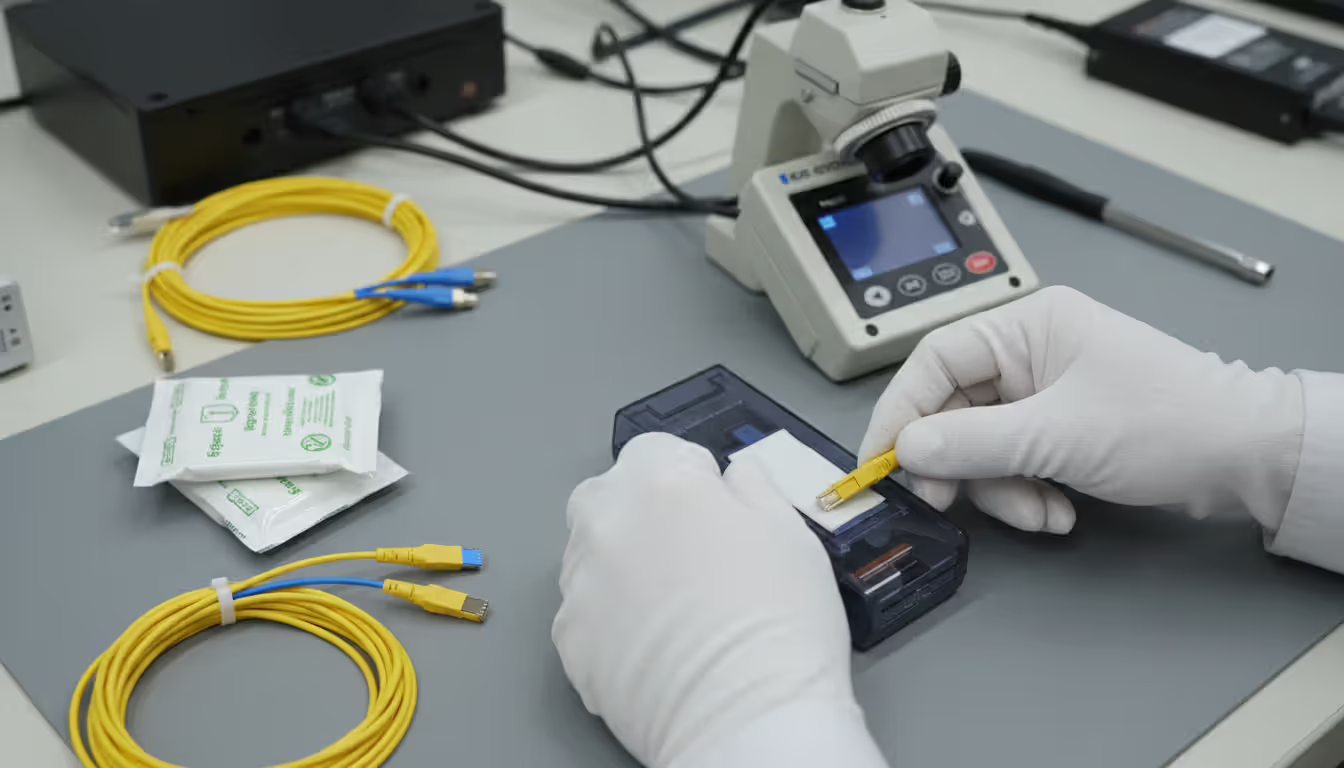
Start with your eyes. Walk the entire cable route looking for obvious problems—sharp bends, pinch points, damaged jacket sections—before conducting optical tests. Inspect every connector end face through a fiber microscope at 200-400x magnification. Scratches, cracks, oil residue, or dust particles visible under magnification will cause connection problems. Clean before testing, then inspect again.
OTDR testing (optical time-domain reflectometry) maps your entire fiber installation by sending light pulses and measuring reflections. The resulting graph shows distance versus signal loss, revealing splice quality, connector performance, and break locations. This creates baseline documentation invaluable for future troubleshooting—when performance degrades three years from now, you'll compare new OTDR traces against originals to pinpoint changes.
Insertion loss measurements determine total signal loss from end to end using calibrated light sources and power meters. Industry standards typically demand less than 0.75 dB loss per connector pair and 0.3 dB per fusion splice on single-mode installations. Multi-mode fiber allows slightly higher losses but should still stay well below 0.5 dB per connector. Anything worse needs rework before acceptance.
Return loss measurements quantify how much light bounces back toward the source from connections and splices instead of traveling forward. Better return loss shows as larger negative numbers—single-mode connectors should hit -40 dB or better. Poor return loss (less negative numbers) creates problems in high-speed bidirectional systems that transmit and receive on the same fiber strand simultaneously.
Documentation needs to be thorough, not decorative. Print or save digital reports showing pass/fail results against your specified standards. Include OTDR traces for each fiber, insertion loss numbers, and return loss readings. These records prove you met contract specifications and establish performance baselines. They also become your best friend when warranty claims arise.
Certification goes beyond basic testing—it means independent verification that your installation meets TIA-568 or manufacturer specifications. Third-party certification costs extra but provides credibility valuable for customer acceptance or warranty protection. Some clients demand it; others accept thorough testing from the installation contractor.
Fiber Optic Multiplexers and Network Equipment
Fiber optic multiplexers solve a common problem: you need more network capacity but installing additional cables costs too much or takes too long. These devices transmit multiple independent data streams simultaneously through one fiber strand by using different wavelengths of light for each stream—similar to how dozens of radio stations broadcast in the same city without interfering because each uses a different frequency.
Dense Wavelength Division Multiplexing (DWDM) crams 40, 80, or 96 separate wavelength channels into a single fiber pair. Each channel operates at a precisely controlled wavelength with incredibly tight spacing—just 0.4 to 0.8 nanometers apart in the 1550 nm spectrum. A 96-channel DWDM setup carrying 400 gigabits per channel pushes 38.4 terabits per second through fiber cables that might have been installed in the 1990s. Suddenly that "old" infrastructure becomes cutting-edge again.
DWDM economics favor high-capacity scenarios. Consider a telecom carrier needing more bandwidth between two data centers 15 miles apart. Option A: excavate streets, install new conduit, pull fresh cables—budget maybe $500,000 and plan on 4-6 months including permits. Option B: install DWDM gear on existing fiber for perhaps $300,000 with completion in 3-4 weeks. Option B wins most of the time unless the existing fiber has problems.
Coarse Wavelength Division Multiplexing (CWDM) takes a less demanding approach with wider channel spacing—20 nanometers between wavelengths supporting typically 8 to 18 channels total. The advantage? CWDM equipment costs dramatically less because it doesn't need temperature-controlled lasers or ultra-precise wavelength tolerances. For organizations needing moderate capacity boosts—total bandwidth in the 10-100 Gbps range—CWDM delivers excellent value on campus networks or metro connections under 80 kilometers.
Multiplexer deployment requires matching your equipment to fiber types and distance requirements. DWDM systems almost always need single-mode fiber and optical amplifiers for distances exceeding 80 kilometers. CWDM works with both single-mode and certain multi-mode fibers but offers limited amplification options, which restricts how far signals can travel before regeneration becomes necessary.
Optical amplifiers provide signal boost without converting light into electrical signals and back again. Erbium-doped fiber amplifiers (EDFAs) can amplify all DWDM channels at once, making transoceanic fiber spans practical. These units need electrical power and occasional maintenance but eliminate the huge expense of regenerating each wavelength individually through separate transponders.
Network equipment choices include matching transceivers to specific fiber types and distance requirements. A 10GBASE-LR transceiver pairs with single-mode fiber for runs up to 10 kilometers. A 10GBASE-SR transceiver works with multi-mode fiber over distances up to 400 meters. Mix these up—use the wrong transceiver type with your fiber—and connections either fail outright or deliver frustratingly unreliable performance.
You know what the most expensive fiber installation actually is? The one where you have to come back and do it again six months later. Sure, quality materials and proper testing cost more initially. But compare that to emergency service calls, network downtime, and the hit your reputation takes when clients remember you as the contractor who cut corners. There's no contest
— Michael Torres
Cost Factors in Fiber Optic Networking Projects
Materials pricing swings wildly based on fiber type, cable construction, and connector selection. Basic outdoor-rated single-mode fiber cable runs anywhere from $0.50 to $2.00 per foot, while armored or specialty variants climb to $5-8 per foot. Indoor plenum-rated cable typically adds 20-40% to the cost compared to riser-rated cable with otherwise similar construction—that fire rating costs real money.
Connectors and termination hardware add $15-75 per fiber endpoint depending on connector type and whether you're field-terminating or using factory assemblies. Pre-terminated cable costs more upfront but saves field labor substantially. Example: a 12-fiber pre-terminated trunk might run $800 compared to $400 for bulk cable plus $360 in connectors and labor—but the pre-terminated version installs faster, with lower failure risk and no need for splicing equipment onsite.
Labor typically represents 40-70% of total project expenses for most fiber optic cable installation work. Skilled fiber technicians command $75-150 per hour depending on regional labor markets and specialization level. Fusion splicing requires specialized training and expensive equipment, adding $15-30 per splice in labor costs. A project requiring 200 splices? That's $3,000-6,000 just in splicing labor before materials or testing.
Equipment investments scale with project complexity. Basic fiber installation requires fusion splicers ($15,000-40,000 to purchase), OTDRs for testing ($8,000-25,000), and cleaning supplies ($500-1,000 to stock properly). Companies doing occasional fiber work often rent equipment at $300-800 daily rather than buying. DWDM systems add multiplexer costs ($50,000-500,000) plus optical amplifiers ($15,000-75,000 each) to the equipment budget.
Installation Method
Cost Range Per Foot
Crew Size Needed
Required Equipment
Daily Production Rate
Aerial (utility pole mounting)
$3-$8
2-3 technicians
Bucket truck, cable lashing tools
500-800 feet
Underground (open trench)
$12-$25
4-5 workers
Trenching machine, conduit, backfill gear
200-400 feet
Underground (directional bore)
$18-$35
3-4 technicians
Boring equipment, locating devices
150-300 feet
Indoor (plenum ceiling spaces)
$5-$12
2 technicians
Ladders, cable pulling equipment
400-700 feet
Indoor (vertical building risers)
$8-$15
2-3 technicians
Scaffolding or lift, cable support systems
200-500 feet
Maintenance expenses stay remarkably low compared to copper networks. Fiber doesn't corrode like copper. Electromagnetic interference doesn't affect it. The cables need no electrical power for signal transmission. Annual maintenance usually involves periodic connector cleaning and occasional OTDR verification testing—figure under $500 yearly for smaller installations. Larger networks need more attention but still cost far less to maintain than equivalent copper infrastructure.
Permits and inspection fees vary dramatically by location. Some municipalities charge flat fees of $50-200 for underground boring permits. Others assess charges based on linear footage or project valuation. Budget roughly 2-5% of your total project cost for permits, required inspections, and utility locating services. Call ahead—permitting timelines sometimes exceed actual construction duration.
Right-of-way expenses can exceed all other costs combined on long-distance projects. Crossing private property requires negotiating easement agreements or ongoing lease payments. Railroad crossings and highway crossings involve application fees ($500-5,000), engineering study requirements, and annual fees that continue indefinitely. Some organizations spend literally years negotiating rights-of-way before installing the first foot of actual cable.
Common Fiber Optic Installation Mistakes to Avoid
Bend radius violations break fibers in ways you won't see. Installers rushing to finish terminations sometimes create tight loops fitting cables into crowded patch panels or force routing around sharp cabinet corners. Initial testing passes, but microcracks develop over weeks and months, gradually increasing signal loss. Always use bend radius limiters and proper routing guides in patch panels and equipment enclosures—they exist for good reasons.
Contamination destroys more fiber connections than all other factors combined. Touch a connector ferrule with your bare finger? You've just deposited skin oils that attract dust like a magnet. Install connectors without microscope inspection? You're gambling that invisible contamination won't cause problems. Clean every single connector before mating—both the plug and the receptacle—regardless of how clean they look to your naked eye. This one habit prevents probably 60% of connection failures.
Author: Logan Kessler;
Source: baltazor.com
Improper splicing techniques create network weak points that haunt you later. Skipping proper fiber cleaning before splicing leaves residue weakening the splice joint. Using wrong fusion parameters for your specific fiber type creates excessive loss. Forgetting splice protection sleeves allows moisture infiltration degrading splices over months or years. Quality fusion splices should display loss under 0.05 dB on the splicer's screen—accept nothing worse without investigation.
Inadequate documentation transforms routine repairs into frustrating detective work. Ever tried identifying one specific fiber in an unlabeled 144-count cable? That's hours of testing to find the right strand. Missing splice maps force technicians to open every single enclosure along a route hunting for a break. Document everything during installation—take photos, record all test results, create clear labeling schemes. This investment saves exponentially more time than it costs when problems arise years later.
Wrong cable types for specific environments guarantee premature failure. Indoor-rated cable installed outdoors? UV exposure degrades the jacket within months. Non-armored cable buried directly without conduit? Rodents view it as a chew toy. Standard dry cable installed in wet underground locations? Water wicks into the core, eventually destroying connections. Match your cable construction to actual environmental conditions, not budget wishful thinking.
Excessive pulling tension snaps fiber strands inside the cable jacket where you can't see the damage. The cable looks perfect externally but fails testing completely. Tension monitors cost $500-1,500 but prevent destroying $10,000 worth of cable during one difficult pull. For complex or long pulls, install pull boxes every 300-500 feet breaking the pull into manageable segments that stay within safe tension limits.
Insufficient cable support creates mechanical stress at termination points over time. Vertical runs without proper support place the cable's entire weight on top terminations, slowly pulling fibers out of connectors through gravity and temperature cycling. Support any vertical cable runs every 4-5 feet and create proper stress relief loops at all termination locations. Physics doesn't care about your budget constraints.
Skipping testing or accepting marginal results creates guaranteed future problems. See a connector showing 1.2 dB loss when specifications demand under 0.75 dB? That connection will probably fail within months as microscopic contamination or mechanical stress gets worse. Re-terminate or re-splice any connection not meeting specifications during initial installation—far cheaper than emergency repairs during production outages with angry users and managers demanding explanations.
Frequently Asked Questions About Fiber Optic Systems
How long does fiber optic cable last?
Properly installed fiber typically remains functional for 25-30 years in most environments, with indoor installations in climate-controlled buildings sometimes exceeding 40 years. The glass fibers themselves essentially don't degrade—they're glass, after all. Cable jackets eventually break down from UV exposure outdoors or environmental factors, but the fiber inside often still works fine. Submarine cables crossing oceans are designed for 25-year service but frequently remain in operation much longer. Plan on periodic testing every 3-5 years to catch degradation before actual failures disrupt service.
What's the difference between single-mode and multi-mode fiber?
Single-mode fiber uses a narrow 8-10 micron core forcing light to travel essentially one straight path, which enables distances up to 40+ kilometers using laser sources before needing amplification. Multi-mode fiber features a wider 50-62.5 micron core accepting multiple simultaneous light paths, which limits practical distances to 300-550 meters but costs significantly less for shorter runs using LED sources. Choose single-mode when building campus backbones connecting buildings or any telecommunications application spanning significant distances. Go with multi-mode for data center interconnects under 400 meters where equipment costs matter more than absolute maximum distance capabilities.
Can I install fiber optic cable myself?
Homeowners and small businesses can absolutely install pre-terminated fiber assemblies without specialized equipment—just route cables carefully respecting bend radius and plug in the factory-installed connectors. Field termination and fusion splicing? That requires equipment costing $20,000+, specialized training, and considerable practice before achieving consistently reliable results. Most organizations hire certified installers for anything beyond running and connecting pre-made cable assemblies. Failed DIY installations usually cost more fixing than hiring professionals would have cost initially—false economy at its finest.
How much does fiber optic installation cost per foot?
Expect $3-8 per foot for aerial installation along utility poles, climbing to $18-35 per foot for directional boring underground—these ranges include both materials and labor. Indoor installation typically runs $5-15 per foot depending on plenum rating requirements and how difficult accessing the route is. Remember these are rough averages for straightforward projects—complex installations with extensive splicing, challenging terrain, or specialized equipment requirements cost substantially more. Always get detailed quotes itemizing materials, labor, testing, and documentation rather than making decisions based on simplified per-foot estimates that hide important details.
What are fiber optic multiplexers used for?
Multiplexers boost fiber capacity by sending multiple independent data streams on different light wavelengths through a single fiber strand simultaneously. Organizations deploy DWDM multiplexers adding 40-96 channels of 100-400 Gbps capacity each to existing fiber, avoiding expensive new cable installation projects. CWDM multiplexers deliver 8-18 channels at lower cost for moderate capacity increases. Multiplexing makes financial sense when fiber capacity limitations throttle network growth but installing fresh cables would cost significantly more than adding multiplexing equipment to infrastructure you already own.
Is fiber optic better than copper cable?
Fiber delivers dramatically higher bandwidth (terabits versus gigabits), reaches much longer distances without amplification (40+ kilometers versus 100 meters maximum), completely ignores electromagnetic interference that plagues copper, provides better security through lack of electromagnetic emissions that could be intercepted, and costs less long-term despite higher installation expenses upfront. Copper still makes sense for very short connections under 100 meters where infrastructure already exists and you're not planning major bandwidth increases. But virtually all new backbone and inter-building installations choose fiber because the advantages become increasingly obvious as bandwidth demands grow over time.
Fiber optic technology delivers the foundation supporting modern high-speed networks—from residential gigabit internet to transcontinental data transmission moving between continents. Understanding practical differences between single-mode and multi-mode fiber, learning proper installation techniques, and knowing when equipment like multiplexers makes sense helps organizations make infrastructure decisions they won't regret.
Successful fiber optic installation demands careful planning, quality materials, proper techniques, and thorough testing. Cutting corners during installation creates problems costing far more to fix than doing things correctly from the start. Professional installation using quality components pays returns through decades of reliable, high-performance connectivity supporting whatever bandwidth demands the future brings.
Bandwidth requirements keep growing—they always have and probably always will. Fiber optic networks provide scalability meeting future needs without replacing physical infrastructure. A fiber network properly installed in 2026 will likely serve effectively into the 2050s and beyond, with periodic equipment upgrades providing capacity increases as technology advances. This longevity makes fiber optic infrastructure one of the most cost-effective technology investments available anywhere.
Software-defined WAN transforms network architecture by enabling intelligent traffic routing across multiple connection types. Learn how SD-WAN works, security considerations, deployment options, and when your business should adopt this technology for improved performance and cost savings
Remote work has made remote access essential for millions. This comprehensive guide explains remote access meaning, compares VPN solutions against remote desktop programs, covers security risks, and helps you choose the right remote access program for your needs
Multi cloud architectures now power 87% of enterprise infrastructure strategies. This comprehensive guide examines how multi cloud works, why businesses adopt it, key components including platforms, storage, data architecture, and IAM, plus practical strategies for implementation and management
Hybrid cloud combines on-premises infrastructure with public cloud services through secure, orchestrated connections. This comprehensive guide covers hybrid cloud architecture, common deployment models, security best practices, implementation challenges, and when organizations should choose a hybrid cloud environmen
The content on this website is provided for general informational and educational purposes only. It is intended to explain concepts related to cloud computing, computer networking, infrastructure, and modern IT systems.
All information on this website, including articles, guides, and examples, is presented for general educational purposes. Technology implementations may vary depending on specific environments, business needs, infrastructure design, and technical requirements.
This website does not provide professional IT, engineering, or technical advice, and the information presented should not be used as a substitute for consultation with qualified IT professionals.
The website and its authors are not responsible for any errors or omissions, or for any outcomes resulting from decisions made based on the information provided on this website.